92/38, No.12 Street, Quarter 18, Binh Hung Hoa Ward, Binh Tan District, Ho Chi Minh City, Vietnam.

Well Commander System Series

Well Commander System Series

Price: Contact

  • Model: 22WC / 22DWC DuPlex / 22TWC TriPlex
  • Trademark: OCV
  • Origin: USA
  • Well Commander System Series

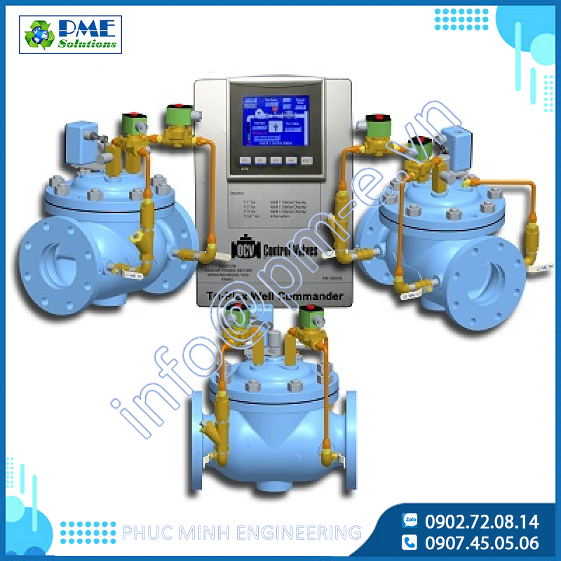
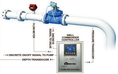
    The OCV “Well Commander System” provides control of well/aquifer levels to prevent over pumping. The Well Commander System can be as simple as one valve, one well and one electronic multi-stage controller , or as complex as three valves, three wells and one electronic multi-stage controller . The electronic controller operates the valve via line pressure through two solenoids (opening and closing). The traditional hydraulic function works in conjunction with the electronic options to provide digital interfacing, remote operation and more precise control over a larger operation span.

    Available models: Well Commander (WC), DuPlex Well Commander (DWC) and TriPlex Well Commander (TWC)

    Valve Features

    • Primary Control of well depth via level/depth transducer*

    • Secondary control of:

      • Output flow rate via flow meter transducer*

      • Valve discharge pressure via pressure transducer*

    • Allows for frequent set point change of control type selected

    • The controls for each well can be operated in either manual or automatic mode

    • Model 115-36 digital control valve(s) with dual solenoid and ‘hydraulic’ reverse flow check

    • The valve(s) opens slowly on pump start and close slowly prior to pump shutdown

    • Scheduling for the control of the valve(s) (time, day of week, flow limiting, process variables)

    • Volume totalizer for the valve(s) output sequence (when used with a flow meter)

    • Remote operation and monitoring of the valve(s) and discrete pump run conditions

    • Remote set point by digital SCADA access

    • Extreme stability over wide range of operation

    • Wider range of flow control than standard hydraulic systems

    • Full function PID controller

    *Only one process variable is in control at any given time but they may all be monitored simultaneously.
    *Sensors/transducers are user supplied.

    STORM WATER COLLECTION POINT

    The Well Commander System can assist in compliance with regulations regarding pumping into the city storm water system. The Well Commander System can measure the wet well depth, limit the volume and control the rate the water is pumped into the city storm water system, all without the need of personnel standing by to monitor or control the system. Options may also be added to email/text messages regarding when the system is pumping, how much is being pumped and at what volume.
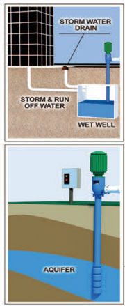
wcfeatrues1

    WELL CONTROL

    The Well Commander System can act as a critical tool to keep applications compliant with limitations regulating pumping from wells. Once the pump is star ted, the valve can control depth, flow, pressure or any combination thereof, until a user selected set point, usually a maximum volume. A restart set point can be set to allow an automatic restart (during a valid run condition) until the stop condition is again valid. The Well Commander System may also be programmed to set off alarms, automatically stop or send an email/text warning when the allowed conditions have been exceeded.

    wcf2


    Valve Operation

    THE WELL COMMANDER WITH A MODEL 115-36 DIGITAL CONTROL VALVE

    Initial setup has been performed for the well(s), which includes user selection of the mode of control desired.

    STARTUP CONTROL SEQUENCE:

    The controller receives a valid run command. It then checks to make sure well depth is above minimal level (user selection 1) and there is no flow before star ting the pump. The controller star ts the pump against the closed valve until the star t-up delay times out. The controller selected input mode then opens the valve at an adjustable, controlled rate. The controller will then control the selected input by positioning the valve (open or close) by the solenoid pilots (2 and 3) to maintain the user selected set point.

    CASE 1:

    Controlling Well Depth: In this mode the user selects three (3) set points:
    1) WDC- Well Depth Control
    2) WDA – Well Depth Alarm (lowest allowed depth)
    3) WDR – Well Depth Recovery (restart point)

    CASE 2:

    Controlling Well Flow: In this mode the user selects three (3) set points:
    1) WFC- Well Flow Output Control
    2) WDA – Well Depth Alarm (lowest allowed depth)
    3) WDR – Well Depth Recovery (restart point)

    CASE 3:

    Controlling Valve Outlet Pressure: In this mode the user selects three (3) set points:
    1) OPC- Valve Outlet Pressure Control
    2) WDA – Well Depth Alarm (lowest allowed depth)
    3) WDR – Well Depth Recovery (restar t point)

    If during any of the 3 modes of operation above the well drops below the WDA preset depth, the system will trigger to stop, alarm, or warn the user (user selectable). The Well Commander will only restart** when the WDR depth has been reached or by user intervention (remote or local).
    **Restart will only happen during a valid run command.

    SHUT-DOWN CONTROL SEQUENCE:

    When the controller run command becomes invalid, the controller will close the valve(s) at an adjustable, controlled rate, and after the valve(s) has closed, the pump will shut off.

    HYDRAULIC REVERSE FLOW CHECK FEATURE:

    Should the pump lose discharge pressure while continuing to run, the “check feature” (6A and 6B) closing will shut off the power to the pump. If power is lost to the system, the “check feature” also closes the valve(s). The check closing will not be instant, thus there is potential for a minimum amount of reverse flow. The pump should be equipped with a non-reverse ratchet.

    INSTALLATION:

    The Well Commander controller should be located within 2,500 ft. of all transducers in order to accurately control the Model 115-36 Digital Control Valve(s). The wiring from the transducers to the controller shall be 20 AWG twisted pair shielded cable in accordance with any local low voltage code requirements. Wiring size to the valve solenoids shall be a minimum of 18 AWG and should follow local electrical codes for voltage level being used.

    Consult factory on applications that do not meet the recommended.

    wcoperations


    Related projects

    Online support
  • Consulting - Quotation
    Consulting - Quotation
  • Consulting-Technical
    Consulting-Technical
  • Consulting - Quotation
    Consulting - Quotation
  • Consulting - Technical
    Consulting - Technical
  • Consulting - Quotation
    Consulting - Quotation